6 构件计算及断面选择
6.1 铁塔构件计算及断面选择
6.1.1 轴心受力构件的强度计算应符合下列规定:
式中:N——轴心拉力或轴心压力设计值(N);
m——构件强度折减系数,应按表6.1.1取值;
An——构件净截面面积(mm2);对多排螺栓连接的受拉构件,要计及锯齿形破坏情况;
f——钢材的强度设计值(N/mm2)。
表6.1.1 构件强度折减系数

6.1.2 轴心受压构件的稳定计算应符合下列规定:

对轴心受压构件:

对压弯构件:

式中:A——构件毛截面面积(mm2);
λ——构件长细比,当λ<30时,取λ=30;当λ>100时,取λ=100;
fy——钢材的强度标准值(N/mm2);
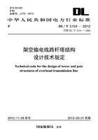
mN——压杆稳定强度折减系数,根据翼缘板自由外伸宽度b(图6.1.2)与厚度t之比计算确定;
φ——轴心受压构件稳定系数,按第6.1.3条确定。

图6.1.2 翼缘板自由外伸宽度示意图
6.1.3 轴心受压构件稳定系数应根据下列规定确定:
1 等边单角钢构件绕最小轴失稳时,按附录C确定;
2 格构式组合结构,根据附录C表C.0.1-1中公式算出换算长细比,再按表C.0.1-2和表C.0.1-3确定;
3 双轴对称十字形截面组合角钢构件(图6.1.3),按公式6.1.3计算其等效回转半径,再按附录C确定。

式中:rt——十字断面等效回转半径,rt≥rx或rt≥ry或rt≥ru时,取rt=rx或rt=ry或rt=ru;
b1——十字断面形心至边缘的距离(mm);
L——构件计算长度(mm)。

图6.1.3 双轴对称十字形截面组合角钢构件示意图
6.1.4 受弯构件计算:

式中:Mx、My——绕x轴和y轴的弯矩设计值(N·mm);
Wx、Wy——对x轴和y轴的截面抵抗矩(mm3)。
6.1.5 压弯构件弯矩平面内的稳定计算:

式中:M——弯矩设计值(N·mm);
W——截面抵抗矩(mm3);
E——钢材的弹性模量(N/mm2);
λx——构件绕x-x轴的长细比;
NEX——参数。
6.1.6 拉弯构件弯矩平面内的强度计算:

6.1.7 轴心受压构件应按下式计算剪力:

注:1 剪力Vs值可认为沿构件全长不变。
2 对格构式轴心受压构件,剪力Vs应由承受剪力的缀材面(包括用整体板连接的面)分担。
6.1.8 构件的计算长度应符合下列规定:
1 主材计算长度按表6.1.8-1采用。
2 交叉斜材计算长度按表6.1.8-2采用。
3 K型斜材计算长度按表6.1.8-3采用。
表6.1.8-1 主材计算长度表

续表6.1.8-1

注:角钢为等边角钢。
表6.1.8-2 交叉斜材计算长度表

续表6.1.8-2

注:1 角钢为等边角钢。
2 图例1、2、4、5交叉斜材在交叉处均不允许断开,图例3交叉斜材在交叉处可以断开。
3 K为交叉斜材计算长度修正系数,按第6.1.9条计算确定。
表6.1.8-3 K型斜材计算长度表

注:1 角钢为等边角钢。
2 塔腿斜材计算长度应乘以1.2增大系数。
3 当交于主材同一点的相邻斜材均为压杆时,斜材选材容许长细比可取同辅助材。
4 图例3和图例4所示平连杆应视作受力构件与塔体同时计算,其中α为平连杆与斜材的刚度比。
6.1.9 交叉斜材计算长度修正系数,按下式计算确定:
两根斜材一拉一压时:
两根斜材同时受压时:
式中:N——所计算杆的内力(N),取绝对值;
N0——相交另一杆的内力(N),取绝对值;两根斜材同时受压时,取N0≤N。