上QQ阅读APP看本书,新人免费读10天
设备和账号都新为新人
5.6 封头及节流孔板计算
5.6.1 椭圆形封头壁厚计算应符合下列规定:
1 最小壁厚计算时(图5.6.1-1)可按式5.6.1-1或式5.6.1-2计算。

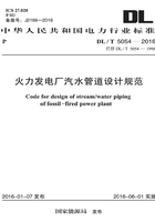
图5.6.1-1 椭圆形封头

式中:Di——封头内径,取相连管道的最大内径(mm);
D0——封头外径,取相连管道的最大外径(mm);
K′——椭圆形封头的椭圆形状系数;
hi——封头内曲面深度;
[σ]t——设计温度下材料许用应力(MPa);
p——设计压力(MPa);
η——焊接接头系数,可根据对接焊缝形式及无损检测的长度比例确定,可按表5.6.1的规定确定。
表5.6.1 焊接接头系数表

2 椭圆形封头取用壁厚应按下式进行计算:
式中:S——椭圆型封头计算壁厚(mm);
C1——钢板厚度负偏差附加值(mm);按照钢板产品技术条件中规定的板厚负偏差百分数确定,应考虑钢板加工减薄量。
5.6.2 平封头壁厚应按下式进行计算:

式中:Di——封头内径,取相连管道的最大内径(mm);
K′、φ′——与封头结构有关的系数,可按表5.6.2的规定选取;
[σ]t——设计温度下材料许用应力(MPa);
p——设计压力(MPa)。
表5.6.2 封头结构形式系数

续表5.6.2

5.6.3 夹在两法兰之间的节流孔板以及中间堵板、回转堵板的厚度计算可按平封头的厚度计算公式5.6.2-1计算,其K′值取0.45,焊接式节流孔板厚度可按平封头厚度计算公式5.6.2-1计算,其K′值取0.6。