7.4 介质比容变化大的蒸汽管道压力损失
7.4.1 本节适用于蒸汽管道终端和始端的介质比容比大于1.6或压降大于初压40%的蒸汽管道的管道压降计算。
7.4.2 管道的压降应按下式计算:

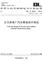
式中:k——绝热指数,对于过热蒸汽k取1.3,对于饱和温度为225℃的干饱和蒸汽k可取1.135,对于饱和温度为310℃的干饱和蒸汽k可取1.08,其他温度下饱和蒸汽的k值可查图取值(图7.4.2):

图7.4.2 饱和蒸汽的绝热指数
1—度x=1;2—干度;x=0.9
7.4.3 计算时首先应按临界压力或临界比容比判别管道内蒸汽的流动特性是亚临界流动还是临界流动,计算应符合下列规定:
1 临界压力应按下列公式计算:

式中:Pc——临界压力(Pa);
P0——始端滞止压力(Pa);
ν0——始端滞止比容(m3/kg)。
滞止参数p0、ν0根据管道始端介质流速,在焓熵图中求取,也可按式7.4.3-2计算,当计算锅炉安全阀排汽管道时,始端滞止参数可取安全阀入口处参数。

2 临界比容比应按下列公式计算:

式中:βc——介质的临界比容与始端比容之比,也可查图取值(图7.4.3)。

图7.4.3 临界压力比αc和临界比容比βc与总阻力系数ξt的关系曲线
3 蒸汽临界流速应按下列公式计算:

或
式中:ωc——临界流速(m/s)。
7.4.4 介质比容变化大的管道应根据不同的已知条件进行水力计算,水力计算可采用以下方法:
1 当已知始端滞止参数p0、ν0、质量流速![]() 、管道总阻力系数ξt和末端空间压力p′时,应按下列方法计算:
、管道总阻力系数ξt和末端空间压力p′时,应按下列方法计算:
1)按式7.4.3-1计算临界压力pc并与p′,比较;
2)当pc小于p′,则为亚临界流动,管道终端蒸汽压力P2取p′,管道终端蒸汽比容应按下列公式计算:

介质比容比β应按下式计算:
管道始端参数应按下列公式计算:

3)如pc大于或等于p′,则为临界流动,管道终端蒸汽压力P2取Pc,管道终端蒸汽比容按下列公式计算:

介质临界比容比βc应按式7.4.3-3计算或查图取值(图7.4.3)。
介质临界压力比αc应按下式计算,或查图取值(图7.4.3)。

管道始端参数应按下列公式计算:

式中:αc——临界压力比;
βc——介质临界比容比。
2 当已知始端参数p1、ν1、质量流速![]() 、管道总阻力系数ξt时,终端参数p2、ν2应按下列方法计算:
、管道总阻力系数ξt时,终端参数p2、ν2应按下列方法计算:
1)按式7.4.4-10计算管道终端与始端介质比容比β,计算出β后与按式7.4.3-3计算βc值比较;

2)如β小于βc,则为亚临界流动,管道的终端参数可按下列公式计算:

3)当β等于βc,则为临界流动,按式7.4.4-6计算临界压力比αc,管道终端参数可按下列公式计算:

4)如β大于βc,表示给定的条件不成立,即在给定的始端参数和总阻力系数达不到给定的质量流速值。
3 当已知始端参数P1、ν1、管道总阻力系数ξt和末端空间压力p′时,质量流速![]() 应按下列方法计算:
应按下列方法计算:
1)按式7.4.4-15计算比值α′并与按式7.4.4-6计算出的αc比较;
2)当α′小于αc,则为亚临界流动,管内介质质量流速![]() 的近似值可按式7.4.4-17计算,其中近似的β值可按式7.4.4-18或7.4.4-19计算,按式7.4.4-1求出管道终端介质比容ν2,再按式7.4.4-16计算出较准确的β值后,代入式7.4.4-17修正
的近似值可按式7.4.4-17计算,其中近似的β值可按式7.4.4-18或7.4.4-19计算,按式7.4.4-1求出管道终端介质比容ν2,再按式7.4.4-16计算出较准确的β值后,代入式7.4.4-17修正![]() 值。
值。

式中:α′——管道始端压力与末端压力空间压力比。
3)当α′大于或等于αc,则为临界流动,管内介质质量流速应按下式计算。

7.4.5 对于终端为亚临界流动的蒸汽管道可采用虚拟法计算(图7.4.5),假设将管道按等截面延长到点“3”,该点在流量不变的条件下为临界状态,相关计算宜符合下列规定:
1 “3”点处参数P3、ν3(图7.4.5)可按式7.4.3-1和式7.4.4-5计算;
2 1段~3段的阻力系数ξ13(图7.4.5)可按下式计算:

3 2段~3段的阻力系数ξ23(图7.4.5)可按下列公式计算:

或

图7.4.5 亚临界流动管道虚拟计算图
4 计算出以上的参数后,根据不同的已知条件采用本规范第7.4.5条第2款~5款中的方法,可求出“2”点或“1”点处的介质参数。
7.4.6 本规范第7.4.1条至第7.4.5条的规定仅适用于介质质量流速![]() 不变的情况。当质量流速
不变的情况。当质量流速![]() 不同时,可按不同的质量流速分段顺序计算,每个局部变换后管道的始端压力应计入异径管或三通等局部变换处动压力的改变,相关参数计算可按下列规定:
不同时,可按不同的质量流速分段顺序计算,每个局部变换后管道的始端压力应计入异径管或三通等局部变换处动压力的改变,相关参数计算可按下列规定:
1 当a等于![]() 且小于1,c等于pdI/pd且小于0.05时,或α大于1,c小于0.03时,蒸汽管道局部变换后的始端压力可按下式计算:
且小于1,c等于pdI/pd且小于0.05时,或α大于1,c小于0.03时,蒸汽管道局部变换后的始端压力可按下式计算:

局部变换后管道始端静压力可按下式计算:
局部变换后始端蒸汽比容可按下式计算:

式中:νⅡ——局部变换后管道始端的蒸汽比容(m3/kg);
![]() ——局部变换后管道始端的质量流速[kg/(cm2·s)]。
——局部变换后管道始端的质量流速[kg/(cm2·s)]。
2 当a小于1、c大于或等于0.05或a大于1、c大于或等于0.03时,可按式7.4.6-4计算局部变换后管道始端与局部变换前管道始端的介质比容比,或查图取β值(图7.4.6-1)。


图7.4.6-1 比容比β与质量流速比a2和动静压比c的关系曲线
(a)a<1;(b)a>1
β值求出后局部变换后管道始端参数可按下列公式计算:

7.4.7 蒸汽在通过异径管向大直径管道流动时,也有达到临界流速的可能。异径管变换后始端的全压应大于或等于后段管子阻力和管子末端背压所形成的压头加上相应于大端的异径管的阻力所形成的压头之和,其相对关系可按下式计算:

式中:P″——后段管子阻力和管子末端背压所形成的压头(Pa);
![]() ——相应于大端的异径管的阻力系数;
——相应于大端的异径管的阻力系数;
ξⅡ——可由本规范附录D查取;
di——异径管的小端内径(mm)。